


 Yeni Kayıt


 Konudaki Resimler


Bildirim
üç faz motor control devre
Daha Fazla 
Bu Konudaki Kullanıcılar:
Daha Az 
2 Misafir - 2 Masaüstü

Giriş
Mesaj
-
-
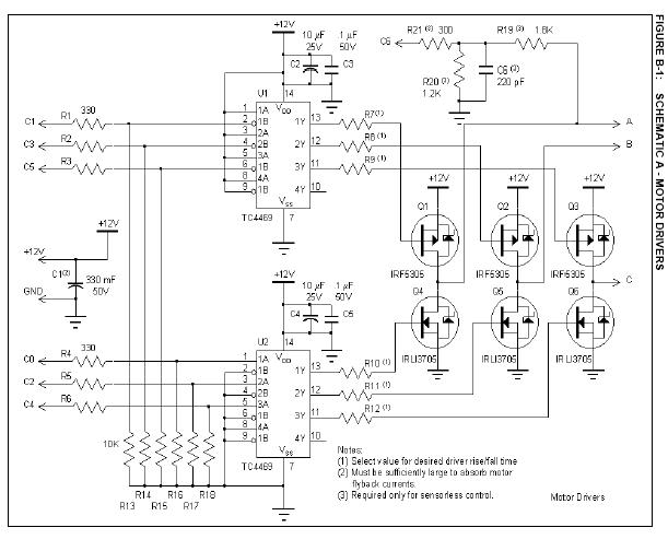
APPENDIX D: SENSORLESS CODE
;************************************************************
; *
; Filename: snsrless.asm *
; Date: 14 Jan. 2002 *
; File Version: 1.0 *
; *
; Author: W.R. Brown *
; Company: Microchip Technology Incorporated *
; *
; *
;************************************************************
; *
; Files required: p16f877.inc *
; *
; *
; *
;************************************************************
; *
; Notes: Sensorless brushless motor control *
; *
; Closed loop 3 phase brushless DC motor control. *
; Two potentiometers control operation. One potentiometer (A0) *
; controls PWM (voltage) and RPM (from table). The other *
; potentiometer (A1) provides a PWM offset to the PWM derived *
; from A0. Phase A motor terminal is connected via voltage *
; divider to A3. This is read while the drive is on during *
; phase 4. The result is the peak applied voltage (Vsupply). *
; A3 is also read while the drive is on at two times during *
; phase 5. The result is the BEMF voltage. The BEMF voltage is *
; read at the quarter (t1) and mid (t2) points of the phase 5 *
; period. BEMF is compared to VSupply/2. If BEMF is above *
; VSupply/2 at t1 and below VSupply/2w at t2 then no speed *
; adjustment is made. If BEMF is high at both t1 and t2 then *
; the speed is reduced. If BEMF is low at t1 and t2 then the *
; speed is increased. *
; *
;************************************************************
;
list P = PIC16F877
include "p16f877.inc"
__CONFIG _CP_OFF & _WRT_ENABLE_OFF & _HS_OSC & _WDT_OFF & _PWRTE_ON & _BODEN_ON
; Acceleration/Deceleration Time = RampRate * 256 * 256 * Timer0Timer0 prescale / Fosc
#define AccelDelay D’100’ ; determines full range acceleration time
#define DecelDelay D’10’ ; determines full range deceleration time
#define ManThresh 0x3f ; Manual threshold is the PWM potentiomenter
; reading above which RPM is adjusted automatically
#define AutoThresh 0x100-ManThresh
OffMask equ B’11010101’ ; PWM off kills the high drives
Invalid equ B’00000000’ ; invalid
Phase1 equ B’00100001’ ; phase 1 C high, A low
Phase2 equ B’00100100’ ; phase 2 C high, B low
Phase3 equ B’00000110’ ; phase 3 A high, B low
Phase4 equ B’00010010’ ; phase 4 A high, C low
Phase5 equ B’00011000’ ; phase 5 B high, C low
Phase6 equ B’00001001’ ; phase 6 B high, A low
#define CARRY STATUS,C
#define ZERO STATUS,Z
#define subwl sublw
;************************************************************
;*
;* Define I/O Ports
;*
#define ReadIndicator PORTB,0 ; diagnostic scope trigger for BEMF readings
#define DrivePort PORTC ; motor drive and lock status
;************************************************************
;*
;* Define RAM variables
;*
CBLOCK 0x20
STATE ; Machine state
PWMThresh ; PWM threshold
PhaseIndx ; Current motor phase index
Drive ; Motor drive word
RPMIndex ; RPM Index workspace
ADCRPM ; ADC RPM value
ADCOffset ; Delta offset to ADC PWM threshold
PresetHi ; speed control timer compare MS byte
PresetLo ; speed control timer compare LS byte
Flags ; general purpose flags
Vsupply ; Supply voltage ADC reading
DeltaV1 ; Difference between expected and actual BEMF at T/4
DeltaV2 ; Difference between expected and actual BEMF at T/2
CCPSaveH ; Storage for phase time when finding DeltaV
CCPSaveL ; Storage for phase time when finding DeltaV
CCPT2H ; Workspace for determining T/2 and T/4
CCPT2L ; Workspace for determining T/2 and T/4
RampTimer ; Timer0 post scaler for accel/decel ramp rate
xCount ; general purpose counter workspace
Status ; relative speed indicator status
ENDC
;************************************************************
;*
;* Define Flags
;*
#define DriveOnFlag Flags,0 ; Flag for invoking drive disable mask when clear
#define AutoRPM Flags,1 ; RPM timer is adjusted automatically
; Flags,3 ; Undefined
#define FullOnFlag Flags,4 ; PWM threshold is set to maximum drive
#define Tmr0Ovf Flags,5 ; Timer0 overflow flag
#define Tmr0Sync Flags,6 ; Second Timer0 overflow flag
; Flags,7 ; undefined
#define BEMF1Low DeltaV1,7 ; BEMF1 is low if DeltaV1 is negative
#define BEMF2Low DeltaV2,7 ; BEMF2 is low if DeltaV2 is negative
;***********************************************************
;*
;* Define State machine states and index numbers
;*
sRPMSetup equ D’0’ ; Wait for Phase1, Set ADC GO, RA1->ADC
sRPMRead equ sRPMSetup+1 ; Wait for ADC nDONE, Read ADC->RPM
sOffsetSetup equ sRPMRead+1 ; Wait for Phase2, Set ADC GO, RA3->ADC
sOffsetRead equ sOffsetSetup+1 ; Wait for ADC nDONE, Read ADC->ADCOffset
sVSetup equ sOffsetRead+1 ; Wait for Phase4, Drive On, wait 9 uSec, Set ADC GO
sVIdle equ sVSetup+1 ; Wait for Drive On, wait Tacq, set ADC GO
sVRead equ sVIdle+1 ; Wait for ADC nDONE, Read ADC->Vsupply
sBEMFSetup equ sVRead+1 ; Wait for Phase5, set Timer1 compare to half phase time
sBEMFIdle equ sBEMFSetup+1 ; Wait for Timer1 compare, Force Drive on and wait 9 uSec,
; Set ADC GO, RA0->ADC
sBEMFRead equ sBEMFIdle+1 ; Wait for ADC nDONE, Read ADC->Vbemf
sBEMF2Idle equ sBEMFRead+1 ; Wait for Timer1 compare, Force Drive on and wait 9 uSec,
; Set ADC GO, RA0->ADC
sBEMF2Read equ sBEMF2Idle+1 ; Wait for ADC nDONE, Read ADC->Vbemf
;************************************************************
;*
;* The ADC input is changed depending on the STATE
;* Each STATE assumes a previous input selection and changes the selection
;* by XORing the control register with the appropriate ADC input change mask
;* defined here:
;*
ADC0to1 equ B’00001000’ ; changes ADCON0<5:3> from 000 to 001
ADC1to3 equ B’00010000’ ; changes ADCON0<5:3> from 001 to 011
ADC3to0 equ B’00011000’ ; changes ADCON0<5:3> from 011 to 000
;************************************************************
;**************************** PROGRAM STARTS HERE
;************************************************************
org 0x000
nop
goto Initialize
org 0x004
bsf Tmr0Ovf ; Timer0 overflow flag used by accel/decel timer
bsf Tmr0Sync ; Timer0 overflow flag used to synchronize code execution
bcf INTCON,T0IF
retfie ;
Initialize
clrf PORTC ; all drivers off
clrf PORTB
banksel TRISA
; setup I/O
clrf TRISC ; motor drivers on PORTC
movlw B’00001011’ ; A/D on RA0 (PWM), RA1 (Speed) and RA3 (BEMF)
movwf TRISA ;
movlw B’11111110’ ; RB0 is locked indicator
movwf TRISB
; setup Timer0
movlw B’11010000’ ; Timer0: Fosc, 1:2
movwf OPTION_REG
bsf INTCON,T0IE ; enable Timer0 interrupts
; Setup ADC
movlw B’00000100’ ; ADC left justified, AN0, AN1
movwf ADCON1
banksel PORTA
movlw B’10000001’ ; ADC clk = Fosc/32, AN0, ADC on
movwf ADCON0
; setup Timer 1
movlw B’00100001’ ; 1:4 prescale, internal clock, timer on
movwf T1CON
; setup Timer 1 compare
movlw 0xFF ; set compare to maximum count
movwf CCPR1L ; LS compare register
movwf CCPR1H ; MS compare register
movlw B’00001011’ ; Timer 1 compare mode, special event - clears timer1
movwf CCP1CON
; initialize RAM
clrf PWMThresh
movlw D’6’
movwf PhaseIndx
clrf Flags
clrf Status ;
clrf STATE ; LoopIdle->STATE
bcf INTCON,T0IF ; ensure Timer0 overflow flag is cleared
bsf INTCON,GIE ; enable interrupts
MainLoop
;************************************************************
;
; PWM, Commutation, State machine loop
;
;************************************************************
btfsc PIR1,CCP1IF ; time for phase change?
call Commutate ; yes - change motor drive
PWM
bsf DriveOnFlag ; pre-set flag
btfsc FullOnFlag ; is PWM level at maximum?
goto PWM02 ; yes - only commutation is necessary
movf PWMThresh,w ; get PWM threshold
addwf TMR0,w ; compare to Timer0
btfss CARRY ; drive is on if carry is set
bcf DriveOnFlag ; timer has not reached threshold, disable drive
call DriveMotor ; output drive word
PWM02
call LockTest
call StateMachine ; service state machine
goto MainLoop ; repeat loop
StateMachine
movlw SMTableEnd-SMTable-1 ; STATE table must have 2^n entries
andwf STATE,f ; limit STATE index to state table
movlw high SMTable ; get high byte of table address
movwf PCLATH ; prepare for computed goto
movlw low SMTable ; get low byte of table address
addwf STATE,w ; add STATE index to table root
btfsc CARRY ; test for page change in table
incf PCLATH,f ; page change adjust
movwf PCL ; jump into table
SMTable ; number of STATE table entries MUST be evenly divisible by 2
goto RPMSetup ; Wait for Phase1, Set ADC GO, RA1->ADC, clear Timer0 overflow
goto RPMRead ; Wait for ADC nDONE, Read ADC->RPM
goto OffsetSetup ; Wait for Phase2, Set ADC GO, RA3->ADC
goto OffsetRead ; Wait for ADC nDONE, Read ADC->ADCOffset
goto VSetup ; Wait for Phase4
goto VIdle ; Wait for Drive On, wait Tacq, set ADC GO
goto VRead ; Wait for ADC nDONE, Read ADC->Vsupply
goto BEMFSetup ; Wait for Phase5, set Timer1 compare to half phase time
goto BEMFIdle ; When Timer1 compares force Drive on, Set ADC GO after Tacq,
RA0->ADC
goto BEMFRead ; Wait for ADC nDONE, Read ADC->Vbemf
goto BEMF2Idle ; When Timer1 compares force Drive on, Set ADC GO after Tacq,
RA0->ADC
goto BEMF2Read ; Wait for ADC nDONE, Read ADC->Vbemf
; fill out table with InvalidStates to make number of table entries evenly divisible by 2
goto InvalidState ; invalid state - reset state machine
goto InvalidState ; invalid state - reset state machine
goto InvalidState ; invalid state - reset state machine
goto InvalidState ; invalid state - reset state machine
SMTableEnd
;~~~~~~~~~~~~~~~~~~~~~~~~~~~~~~~~~~~~~~~~~~~~~~
RPMSetup ; Wait for Phase1, Set ADC GO, RA1->ADC, clear Timer0 overflow
movlw Phase1 ; compare Phase1 word...
xorwf Drive,w ; ...with current drive word
btfss ZERO ; ZERO if equal
return ; not Phase1 - remain in current STATE
bsf ADCON0,GO ; start ADC
movlw ADC0to1 ; prepare to change ADC input
xorwf ADCON0,f ; change from AN0 to AN1
incf STATE,f ; next STATE
bcf Tmr0Sync ; clear Timer0 overflow
return ; back to Main Loop
;~~~~~~~~~~~~~~~~~~~~~~~~~~~~~~~~~~~~~~~~~~~~~~
RPMRead ; Wait for ADC nDONE, Read ADC->RPM
btfsc ADCON0,GO ; is ADC conversion finished?
return ; no - remain in current STATE
movf ADRESH,w ; get ADC result
movwf ADCRPM ; save in RPM
incf STATE,f ; next STATE
return ; back to Main Loop
;~~~~~~~~~~~~~~~~~~~~~~~~~~~~~~~~~~~~~~~~~~~~~~
OffsetSetup ; Wait for Phase2, Set ADC GO, RA3->ADC
movlw Phase2 ; compare Phase2 word...
xorwf Drive,w ; ...with current drive word
btfss ZERO ; ZERO if equal
return ; not Phase2 - remain in current STATE
bsf ADCON0,GO ; start ADC
movlw ADC1to3 ; prepare to change ADC input
xorwf ADCON0,f ; change from AN1 to AN3
incf STATE,f ; next STATE
return ; back to Main Loop
;~~~~~~~~~~~~~~~~~~~~~~~~~~~~~~~~~~~~~~~~~~~~~~
OffsetRead ; Wait for ADC nDONE, Read ADC->ADCOffset
btfsc ADCON0,GO ; is ADC conversion finished?
return ; no - remain in current STATE
movf ADRESH,w ; get ADC result
xorlw H’80’ ; complement MSB for +/- offset
movwf ADCOffset ; save in offset
addwf ADCRPM,w ; add offset to PWM result
btfss ADCOffset,7 ; is offset a negative number?
goto OverflowTest ; no - test for overflow
btfss CARRY ; underflow?
andlw H’00’ ; yes - force minimum
goto Threshold ;
OverflowTest
btfsc CARRY ; overflow?
movlw H’ff’ ; yes - force maximum
Threshold
movwf PWMThresh ; PWM threshold is RPM result plus offset
btfsc ZERO ; is drive off?
goto DriveOff ; yes - skip voltage measurements
bcf FullOnFlag ; pre-clear flag in preparation of compare
sublw 0xFD ; full on threshold
btfss CARRY ; CY = 0 if PWMThresh > FullOn
bsf FullOnFlag ; set full on flag
incf STATE,f ; next STATE
return ; back to Main Loop
DriveOff
clrf Status ; clear speed indicators
movlw B’11000111’ ; reset ADC input to AN0
andwf ADCON0,f ;
clrf STATE ; reset state machine
return
;~~~~~~~~~~~~~~~~~~~~~~~~~~~~~~~~~~~~~~~~~~~~~~
VSetup ; Wait for Phase4
movlw Phase4 ; compare Phase4 word...
xorwf Drive,w ; ...with current Phase drive word
btfss ZERO ; ZERO if equal
return ; not Phase4 - remain in current STATE
call SetTimer ; set timer value from RPM table
incf STATE,f ; next STATE
return ; back to Main Loop
;~~~~~~~~~~~~~~~~~~~~~~~~~~~~~~~~~~~~~~~~~~~~~~
VIdle ; Wait for Drive On, wait Tacq, set ADC GO
btfss DriveOnFlag ; is Drive active?
return ; no - remain in current STATE
call Tacq ; motor Drive is active - wait ADC Tacq time
bsf ADCON0,GO ; start ADC
incf STATE,f ; next STATE
return ; back to Main Loop
;~~~~~~~~~~~~~~~~~~~~~~~~~~~~~~~~~~~~~~~~~~~~~~
VRead ; Wait for ADC nDONE, Read ADC->Vsupply
btfsc ADCON0,GO ; is ADC conversion finished?
return ; no - remain in current STATE
movf ADRESH,w ; get ADC result
movwf Vsupply ; save as supply voltage
incf STATE,f ; next STATE
bcf Tmr0Sync ; clear Timer0 overflow
return ; back to Main Loop
;~~~~~~~~~~~~~~~~~~~~~~~~~~~~~~~~~~~~~~~~~~~~~~
BEMFSetup ; Wait for Phase5, set Timer1 compare to half phase time
movlw Phase5 ; compare Phase5 word...
xorwf Drive,w ; ...with current drive word
btfss ZERO ; ZERO if equal
return ; not Phase5 - remain in current STATE
btfss Tmr0Sync ; synchronize with Timer0
return ;
btfss PWMThresh,7 ; if PWMThresh > 0x80 then ON is longer than OFF
goto BEMFS1 ; OFF is longer and motor is currently off - compute now
btfss DriveOnFlag ; ON is longer - wait for drive cycle to start
return ; not started - wait
BEMFS1
bcf CCP1CON,0 ; disable special event on compare
movf CCPR1H,w ; save current capture compare state
movwf CCPSaveH ;
movwf CCPT2H ; save copy in workspace
movf CCPR1L,w ; low byte
movwf CCPSaveL ; save
movwf CCPT2L ; and save copy
bcf CARRY ; pre-clear carry for rotate
rrf CCPT2H,f ; divide phase time by 2
rrf CCPT2L,f ;
bcf CARRY ; pre-clear carry
rrf CCPT2H,w ; divide phase time by another 2
movwf CCPR1H ; first BEMF reading at phase T/4
rrf CCPT2L,w ;
movwf CCPR1L ;
incf STATE,f ; next STATE
return ; back to Main Loop
;~~~~~~~~~~~~~~~~~~~~~~~~~~~~~~~~~~~~~~~~~~~~~~
BEMFIdle ; When Timer1 compares force Drive on, Set ADC GO after Tacq, RA0-
>ADC
btfss PIR1,CCP1IF ; timer compare?
return ; no - remain in current STATE
bsf DriveOnFlag ; force drive on for BEMF reading
call DriveMotor ; activate motor drive
bsf ReadIndicator ; Diagnostic
call Tacq ; wait ADC acquisition time
bsf ADCON0,GO ; start ADC
bcf ReadIndicator ; Diagnostic
; setup to capture BEMF at phase 3/4 T
movf CCPT2H,w
addwf CCPR1H,f ; next compare at phase 3/4 T
movf CCPT2L,w ;
addwf CCPR1L,f ; set T/2 lsb
btfsc CARRY ; test for carry into MSb
incf CCPR1H,f ; perform carry
bcf PIR1,CCP1IF ; clear timer compare interrupt flag
incf STATE,f ; next STATE
return ; back to Main Loop
;~~~~~~~~~~~~~~~~~~~~~~~~~~~~~~~~~~~~~~~~~~~~~~
BEMFRead ; Wait for ADC nDONE, Read ADC->Vbemf
btfsc ADCON0,GO ; is ADC conversion finished?
return ; no - remain in current STATE
rrf Vsupply,w ; divide supply voltage by 2
subwf ADRESH,w ; Vbemf - Vsupply/2
movwf DeltaV1 ; save error voltage
incf STATE,f ; next STATE
return ; back to Main Loop
;~~~~~~~~~~~~~~~~~~~~~~~~~~~~~~~~~~~~~~~~~~~~~~
BEMF2Idle ; When Timer1 compares force Drive on, Set ADC GO after Tacq, RA0-
>ADC
btfss PIR1,CCP1IF ; timer compare?
return ; no - remain in current STATE
bsf DriveOnFlag ; force drive on for BEMF reading
call DriveMotor ; activate motor drive
bsf ReadIndicator ; Diagnostic
call Tacq ; wait ADC acquisition time
bsf ADCON0,GO ; start ADC
bcf ReadIndicator ; Diagnostic
movlw ADC3to0 ; prepare to change ADC input
xorwf ADCON0,f ; change from AN3 to AN0
; restore Timer1 phase time and special event compare mode
movf CCPSaveH,w
movwf CCPR1H ; next compare at phase T
movf CCPSaveL,w ;
movwf CCPR1L ; set T lsb
bcf PIR1,CCP1IF ; clear timer compare interrupt flag
bsf CCP1CON,0 ; enable special event on compare
incf STATE,f ; next STATE
return ; back to Main Loop
;~~~~~~~~~~~~~~~~~~~~~~~~~~~~~~~~~~~~~~~~~~~~~~
BEMF2Read ; Wait for ADC nDONE, Read ADC->Vbemf
btfsc ADCON0,GO ; is ADC conversion finished?
return ; no - remain in current STATE
rrf Vsupply,w ; divide supply voltage by 2
subwf ADRESH,w ; Vbemf - Vsupply/2
movwf DeltaV2 ; save error voltage
clrf STATE ; reset state machine to beginning
return ; back to Main Loop
;~~~~~~~~~~~~~~~~~~~~~~~~~~~~~~~~~~~~~~~~~~~~~~
InvalidState ; trap for invalid STATE index
movlw B’11000111’ ; reset ADC input to AN0
andwf ADCON0,f ;
clrf STATE
return
;____________________________________________________________
Tacq
;************************************************************
;
; Software delay for ADC acquisition time
; Delay time = Tosc*(3+3*xCount)
;
;************************************************************
movlw D’14 ; 14 equates to approx 9 uSec delay
movwf xCount ;
decfsz xCount,f ;
goto $-1 ; loop here until time complete
return
LockTest
;************************************************************
;
; T is the commutation phase period. Back EMF is measured on the
; floating motor terminal at two times during T to determine
; the approximate zero crossing of the BEMF. BEMF low means that
; the measured BEMF is below (supply voltage)/2.
; If BEMF is low at 1/4 T then accelerate.
; If BEMF is high at 1/4 T and low at 3/4 T then speed is OK.
; If BEMF is high at 1/4 T and 3/4 T then decelerate.
;
; Lock test computation is synchronized to the PWM clock such
; that the computation is performed during the PWM ON or OFF
; time whichever is longer.
;
;************************************************************
; synchronize test with start of Timer0
btfss Tmr0Ovf ; has Timer0 wrapped around?
return ; no - skip lock test
btfss PWMThresh,7 ; if PWMThresh > 0x80 then ON is longer than OFF
goto LT05 ; OFF is longer and motor is currently off - compute now
btfss DriveOnFlag ; ON is longer - wait for drive cycle to start
return ; not started - wait
LT05
bcf Tmr0Ovf ; clear synchronization flag
decfsz RampTimer,f ; RampTimer controls the acceleration/deceleration rate
return
; use lock results to control RPM only if not manual mode
bsf AutoRPM ; preset flag
movf ADCRPM,w ; compare RPM potentiometer...
addlw AutoThresh ; ...to the auto control threshold
btfss CARRY ; CARRY is set if RPM is > auto threshold
bcf AutoRPM ; not in auto range - reset flag
btfss BEMF1Low ; is first BEMF below Supply/2
goto LT20 ; no - test second BEMF
LT10
; accelerate if BEMF at 1/4 T is below Supply/2
movlw B’10000000’ ; indicate lock test results
movwf Status ; status is OR’d with drive word later
movlw AccelDelay ; set the timer for acceleration delay
movwf RampTimer ;
btfss AutoRPM ; is RPM in auto range?
goto ManControl ; no - skip RPM adjustment
incfsz RPMIndex,f ; increment the RPM table index
return ; return if Index didn’t wrap around
decf RPMIndex,f ; top limit is 0xFF
return
LT20
btfsc BEMF2Low ; BEMF1 was high...
goto ShowLocked ; ... and BEMF2 is low - show locked
; decelerate if BEMF at 3/4 T is above Supply/2
movlw B’01000000’ ; indicate lock test results
movwf Status ; status is OR’d with drive word later
movlw DecelDelay ; set the timer for deceleration delay
movwf RampTimer ;
btfss AutoRPM ; is RPM in auto range?
goto ManControl ; no - skip RPM adjustment
decfsz RPMIndex,f ; set next lower RPM table index
return ; return if index didn’t wrap around
incf RPMIndex,f ; bottom limit is 0x01
return
ShowLocked
movlw B’11000000’ ; indicate lock test results
movwf Status ; status is OR’d with drive word later
movlw DecelDelay ; set the timer for deceleration delay
movwf RampTimer ;
btfsc AutoRPM ; was RPM set automatically?
return ; yes - we’re done
ManControl
movf ADCRPM,w ; get RPM potentiometer reading...
movwf RPMIndex ; ...and set table index directly
return
Commutate
;************************************************************
;
; Commutation is triggered by PIR1<CCP1IF> flag.
; This flag is set when timer1 equals the compare register.
; When BEMF measurement is active the compare time is not
; cleared automatically (special event trigger is off).
; Ignore the PIR1<CCP1IF> flag when special trigger is off
; because the flag is for BEMF measurement.
; If BEMF measurement is not active then decrement phase table
; index and get the drive word from the table. Save the
; drive word in a global variable and output to motor drivers.
;
;************************************************************
btfss CCP1CON,0 ; is special event on compare enabled?
return ; no - this is a BEMF measurement, let state machine handle this
bcf PIR1,CCP1IF ; clear interrupt flag
movlw high OnTable ; set upper program counter bits
movwf PCLATH
decfsz PhaseIndx,w ; decrement to next phase
goto $+2 ; skip reset if not zero
movlw D’6’ ; phase counts 6 to 1
movwf PhaseIndx ; save the phase index
addlw LOW OnTable
btfsc CARRY ; test for possible page boundary
incf PCLATH,f ; page boundary adjust
call GetDrive
movwf Drive ; save motor drive word
DriveMotor
movf Drive,w ; restore motor drive word
btfss DriveOnFlag ; test drive enable flag
andlw OffMask ; kill high drive if PWM is off
iorwf Status,w ; show speed indicators
movwf DrivePort ; output to motor drivers
return
GetDrive
movwf PCL ; computed goto
OnTable
retlw Invalid
retlw Phase6
retlw Phase5
retlw Phase4
retlw Phase3
retlw Phase2
retlw Phase1
retlw Invalid
SetTimer
;************************************************************
;
; This sets the CCP module compare registers for timer 1.
; The motor phase period is the time it takes timer 1
; to count from 0 to the compare value. The CCP module
; is configured to clear timer 1 when the compare occurs.
; Get the timer1 compare variable from two lookup tables, one
; for the compare high byte and the other for the low byte.
;
;************************************************************
call SetTimerHigh
movwf CCPR1H ; Timer1 High byte preset
call SetTimerLow
movwf CCPR1L ; Timer1 Low byte preset
return
SetTimerHigh
movlw high T1HighTable ; lookup preset values
movwf PCLATH ; high bytes first
movlw low T1HighTable ;
addwf RPMIndex,w ; add table index
btfsc STATUS,C ; test for table page crossing
incf PCLATH,f ;
movwf PCL ; lookup - result returned in W
SetTimerLow
movlw high T1LowTable ; repeat for lower byte
movwf PCLATH ;
movlw low T1LowTable ;
addwf RPMIndex,w ; add table index
btfsc STATUS,C ; test for table page crossing
incf PCLATH,f ;
movwf PCL ; lookup - result returned in W
#include "BLDCspd4.inc"
end
-
Bu web sitesinde de bir devre verilmiş bakarsanız belki size faydalı olabilir.http://home.att.net/~wzmicro/6203drv.html -
Bu devreyi tavsiye edermisiniz arkadaşlar.Başka bir devre önerisi olan varsa lütfen yardım etsin.Şimdiden teşekkürler.
-
devreye bakınca daha çok dc ac konvertöre benziyor.besleme 12 dc fakat motora uygulanan gerilim ac,bunu a,b,c,çıkışlarına bi artı,bi eksi uygulandını gördüğüm için söylüyorum. transistörlerin balantısından öyle anlaşılıyor. -
kardeş eğer butür şeyleri denemeye fazla zamanın yoksa bu o kadar büyütülecek bir şey değil derim ben daha basitte olabilir kendini internetten buldugun devrelerle maceradan maceraya atmak istemiyorsan kendinde bişeyler üretebilirsin ilk önce 3 fazı dc ye çevir bu çok basit bir şekilde tek fazlıdan daha kaliteli bir dc olacaktır sonra zaten gerisi gelir ister pwm ister motorun gerilimini kontrol ederek yapabilirsin motorun ucunada bir takometre(dinamo veya bir dc motor) takarsan geri beslemeli mükemmel bir şey olabilir
eğer yardım istersen sana amatörce yardım edebilirim ugur_mola@hotmail.com -
Aramızda bu konu hakkında bilgisi olan yokmu.Sayın arkadaşlar üç faz motor hız kontrol devresi nereden bulabilirim. -
Microchip sitesinde motorlarla ilgili uygulama notları bölümünde olması lazım. Diğer MCU üreten firmaların da ilgili sayfalarına bakabilirsin. -
sen 3 fazlı dc motor hız kontrolu demişsin bundan kastın ne 3 faz kullanark dc motor kontrol etmekmi yoksa soruyu yanlış mı yazdın 3 fazı kotrol etmekmi istiyorsun yoksa 3 fazla çalışan dc motorlarmı var da haberim yok 
-
4 uçlu HDD motorları bir örnek olabilir mi? -
quote:
3 fazla çalışan dc motorlarmı var da haberim yok
Durum onu gösteriyor. -
erroraesthumanum
doğrudur kendileri 3 phase brushless motor dur. hdd motor u veya spindle motor olarak da geçer.
sürücüler için freescale ( rahmetli motorola ), texas instruments gibi üreticilerin web siteleri ziyaret edilebilir...
-
Sayın arkadaşlar yardımlarınız için çok teşekkürler.Motorun kontrol bağlantısı resimde görüldüğü gibi.Motora 8 adet kablo girişi var.Bunlar resimde görünüyor.Buna göre nasıl bir devre yapmalıyım.


< Bu mesaj bu kişi tarafından değiştirildi sky762005 -- 18 Ocak 2007; 8:20:04 >
-
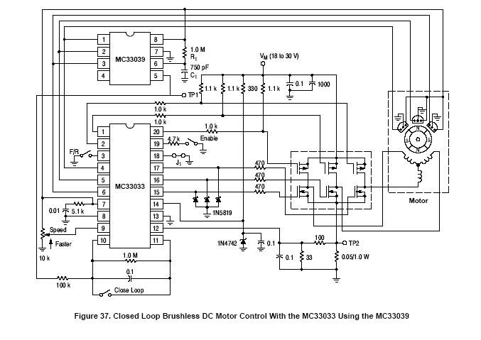
sayın arkadaşlar bu 3 fazlı dc motor nedemek yani çalışma mantıgı nedir niye böyle bişey yapmışlar diğer motorlarla karşılaştırıldıgında daha iyimi randman alınıyor ben şunu anlamadım madem 3fazla çalışıyor niye buna dc motor diyolar bunun mantıgını buraya açıklayabilirseniz bizde yeni bişey ögreniriz ingilizcem 0 türkçe bir kaynak veya sizlerden kısaca bir açıklama gelirse sevinirim -
sayın ugurmola ,
brushless yani fırçasız DC motorlar servo motor olarak kullanılmaktadır
bunlar DC motor mantığıyla çalışır
rotorunda sabit mıknatıslar bulunur
tek fark statorunda 3 faz olmasıdır
bir de DC motorlarda sabit mıknatıs statorda iken
brushless DC motorda rotordadır
rotor hangi fazın önüne gelirse o faza akım verir ( sürücü )
böylece rotora tork uygulanır
rotorun hangi fazın önüne geldiğini de motorun arkasındaki
hall sensor denilen anahtarlarla anlaşılır
böylece sürücü hangi fazı ateşleyeceğini de anlamış olur
neden brushless DC kullanılmaktadır ?
çünkü pratik olarak ömrü çok uzundur
kolay kolay arıza yapmaz
ömrünü belirleyen şey rulmanlarıdır
rulmanın ömrü kadar ömrü vardır -
bildiğiniz 3 fazı bir kenara koyun şimdilik.
motor AC indüksiyon motoru tarzında fırçasız bir yapıya sahip. içerisinde 3 faz sargısı var. bunlar düşük dc gerilimlerle anahtarlanılarak faz sargılarında yani statorda döner alan oluşturuluyor. dolaysı ile döner alanın etkisinde kalan rotorda dönmeye zorlanıyor, yapı basit olarak bu. hdd lerde de kullanılan yüksek devirli bir motor tipi... -
anotherbrick emeğin için çok teşekkür ederim çok iyi anladım saol
Sayfa:
1
Ip işlemleri
Bu mesaj IP'si ile atılan mesajları ara Bu kullanıcının son IP'si ile atılan mesajları ara Bu mesaj IP'si ile kullanıcı ara Bu kullanıcının son IP'si ile kullanıcı ara
KAPAT X
Bu mesaj IP'si ile atılan mesajları ara Bu kullanıcının son IP'si ile atılan mesajları ara Bu mesaj IP'si ile kullanıcı ara Bu kullanıcının son IP'si ile kullanıcı ara
KAPAT X

